How to upgrade the antennae on the Motelona
Unfortunately, the cool looking 2" rubber ducky antennae on the Motelona is fake. It's just for looks! It's not legit. It's a cheap Chinese trick!
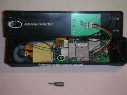
Inside the phone the antennae is stock, meaning it's just a tiny little wire connected to a naked Motorola V180 mainboard. This is clearly unacceptable. A phone like this needs to have a killer antennae, and should be be able to pick up a signal from inside a concrete bunker.
Again, our brick phone loving friends over at www.howardforums.com have a little discussion going about the internals of the Motelona here:
http://www.howardforums.com/showthread.php?t=1305739
It seems that some Motelona phones have the antennae wire completely missing (like mine), but other people have gotten a phone with an unsoldered wire, a wire soldered to the wrong pad (?), and in still other cases people have gotten a phone with an intact antennae wire.
Curiouser and curiouser.
It turns out though, that soldering a plain wire from the antennae to the pad on the mainboard will give you some significant RFI. You know, that classic "cell phone" sound you can hear as feedback on speakers from time to time. That noise is interference from unshielded radio signals. It's also annoying and unnecessary.
Again I'd like to thank Pace1960 at HoFo for the great pictures!
So what can be done about the whole antennae situation?
The user Pace1960 at the HowardForums mobile phone chatboard has a few ideas. This is what he has to say:
(Original post is here): http://www.howardforums.com/showthread.php?t=1305739&page=2&pp=15
CQ Kilowatt Delta 5 Foxtrot Hotel Whiskey, here is Whiskey 5 Lima Papa Sierra,
Nothing about the antenna output on this phone seems proper. According to the schematics on both the V180 and V220 Motorola units, a chip set called "Eagle" dictates what VCO values are sent to the "stub antenna". I know the antenna wire is just a single piece of wire rather than TRUE coax. The more I think about it, the more CRAPPY this China rig is! You and I both know that an antenna has a "radiating" element AND a "ground plane" element. What is missing in this phone is the balance of the 2.
My 1st order of business is to get a some RG-174 see:
http://www.universal-radio.com/catalog/cable/2632.html
I would use the RG-174 not only for the antenna feed, but the speaker leads as well!
I would solder the center conductor of the RG174 to the square pad and the braid to a full wave 1900Mhz cut of wire taped inside the housing as it's ground plane. I would then solder the center conductor of the 174 to the center pin of the antenna connector and the braid to the threaded part of the antenna connector. While digging and scratching with the soldering iron, I would replace the 2 FAT speaker wires with one run of the 174 coax AS the speaker wires. That should clean up ALL spurious RF leaks! Then, check to see that the advertised 2.5db gain antenna is a "real" antenna, if not, order a USA made injection molded replacement!
There still has to be a "reason" that they didn't just solder the antenna wire to the large square pad! I wanna know why! Ooopss...perhaps they didn't want to use "balanced feed line" like RG174...never mind...that's why. Slap it together and blow it out the door! With the cost of return shipping, most of us will just drop the phone in the nearest dumpster. Well, NOT me! I'll gut this puppy and go here:
http://www.telit.com/en/products.ph...3&p_ac=show&p=7
A good idea always has room for improvement
and or, put that in your pipe and smoke it!
73's from
W5LPS
So what does any of that mean?
Well, I'm not an expert, but it would seem that Pace1960 is a HAM or Amateur radio guy, and has a little bit of knowledge about how an antenna should be built. Also, he took all that time to photograph the internals of a Chinese retro brick phone, so I'll take what he has to say under advisement. :)
He mentions the idea of taking a piece of RG-174 and using that as the connection to the antennae, to both shield and properly ground the radio. I think this idea has merit, and should be tried. Unfortunately, all the HoFo posts about the Motelona date back to 2008, so we may never know if Pace1960 ever got around to soldering up a shielded antennae wire or not.
He mentions the idea of taking a piece of RG-174 and using that as the connection to the antennae, to both shield and properly ground the radio. I think this idea has merit, and should be tried. Unfortunately, all the HoFo posts about the Motelona date back to 2008, so we may never know if Pace1960 ever got around to soldering up a shielded antennae wire or not.
I will attempt this modification!
And I will let all you good people know how it works out. I need a peice of shielded cable, and a soldering iron. Stay tuned for developments!
**Update** It wasn't all that great.
Yeah, it turns out that this is all speculation and bullshit. If you just cut the unshielded wire in half (to about 1/2 inch, to better match the cell wavelength) you get much better performance than any messy home-made bench soldering job. Sad but true. Now, if you could hack in a legit connection to an external antennae base, that might be something! Otherwise, just trying to match the wavelength is a better use of your time. Oddly, the phone reception is somewhat sensitive to elevation. During rapid elevation changes (such as a car driving though the mountains) the phone will tend to lose and reacquire signal. I don't know why. It's the brick. It does what it wants to sometimes.
